Scenarios & Selection
Overview
This chapter presents eight representative deployment scenarios that cover the full breadth of critical data transfer use cases encountered in modern enterprise, industrial, and cloud environments. Each scenario is accompanied by a real-world deployment illustration, a detailed description of the security architecture, and a table of primary technical indicators. These scenarios serve as reference blueprints that can be adapted to specific organizational contexts by adjusting scale, redundancy levels, and integration points.
The scenarios are organized from internet-facing API exposure through to zero-trust remote access, covering the most common threat surfaces where data interception, tampering, or unauthorized access occurs. Engineers should use these blueprints as starting points and apply the decision logic from Chapter 2 to select the appropriate controls for each flow in their own environment.
Scenario A — Internet-Facing API Security (North-South Traffic)
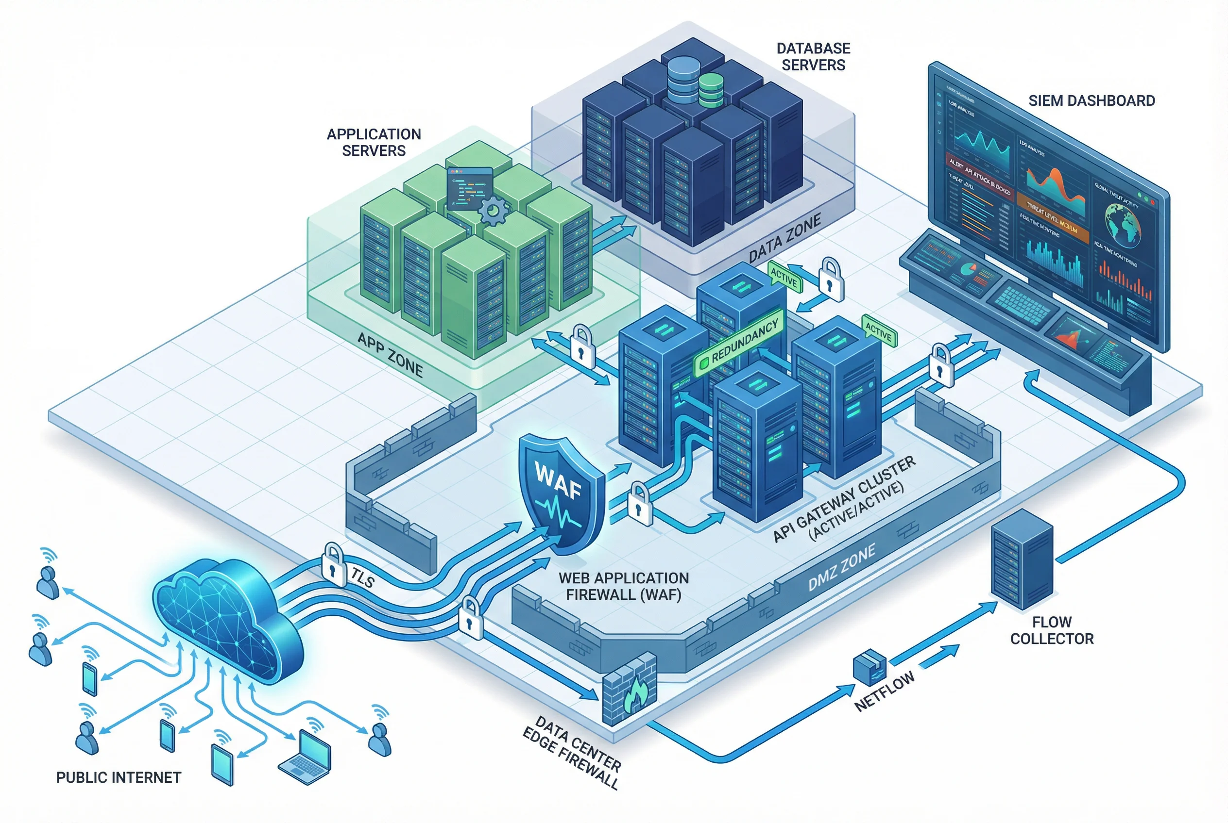
This scenario addresses the most common enterprise exposure: public-facing APIs consumed by web browsers, mobile apps, and third-party integrations. The architecture places an active-active API gateway cluster in the DMZ, fronted by a WAF for application-layer filtering. All inbound connections terminate TLS at the gateway boundary; re-encryption with mTLS is applied for backend service calls. NetFlow data is exported from the edge firewall to a central collector, and all authentication events and API call logs are ingested by the SIEM for real-time correlation.
Scenario B — Microservices mTLS East-West Traffic
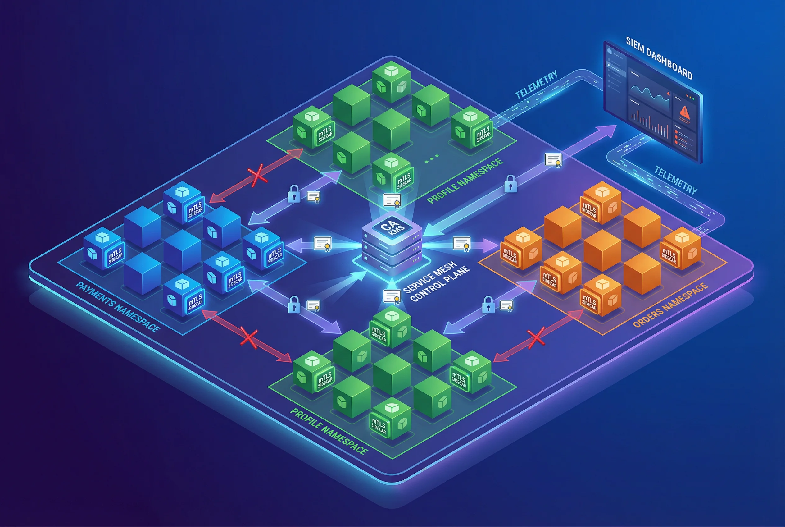
As organizations adopt microservices architectures on Kubernetes, east-west traffic between services becomes a significant attack surface. This scenario deploys a service mesh with mTLS sidecars on every pod, managed by a central control plane that issues short-lived certificates from the PKI/KMS. Namespace-level network policies restrict which services can communicate, and all sidecar telemetry is exported to the SIEM. The control plane enforces certificate rotation automatically, eliminating the risk of long-lived credentials in service-to-service communication.
Scenario C — Data Center IPsec Replication (Site-to-Site)
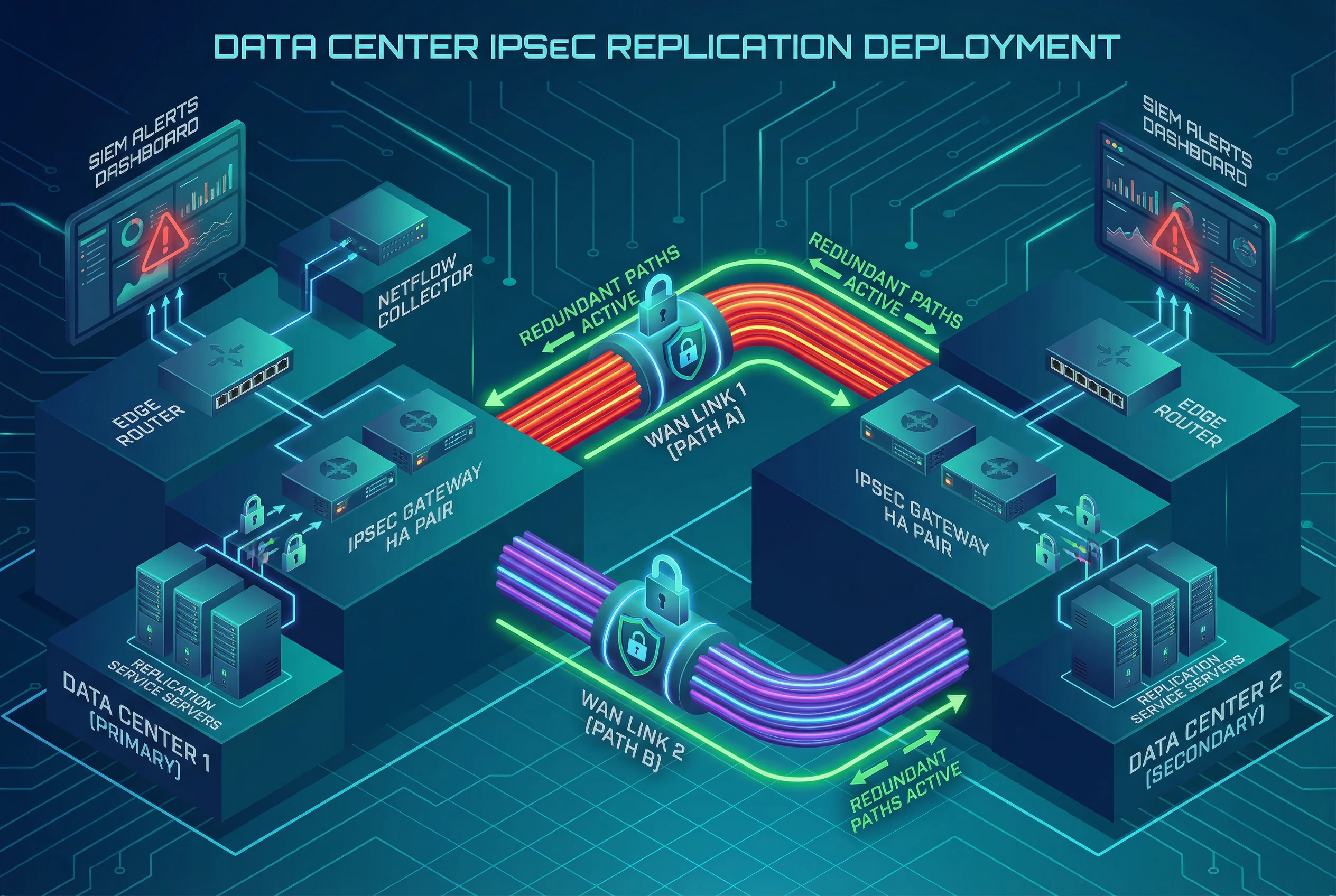
Critical data replication between primary and secondary data centers requires a robust site-to-site encryption mechanism that can sustain high throughput with low latency overhead. This scenario deploys IPsec gateway pairs in HA configuration at each site, connected via two diverse WAN paths to eliminate single points of failure. Route-based IPsec is preferred over policy-based to simplify management and support dynamic routing. NetFlow is exported from both edge routers to a shared collector, and the SIEM monitors tunnel health, rekey events, and traffic anomalies.
Scenario D — Partner B2B Data Exchange
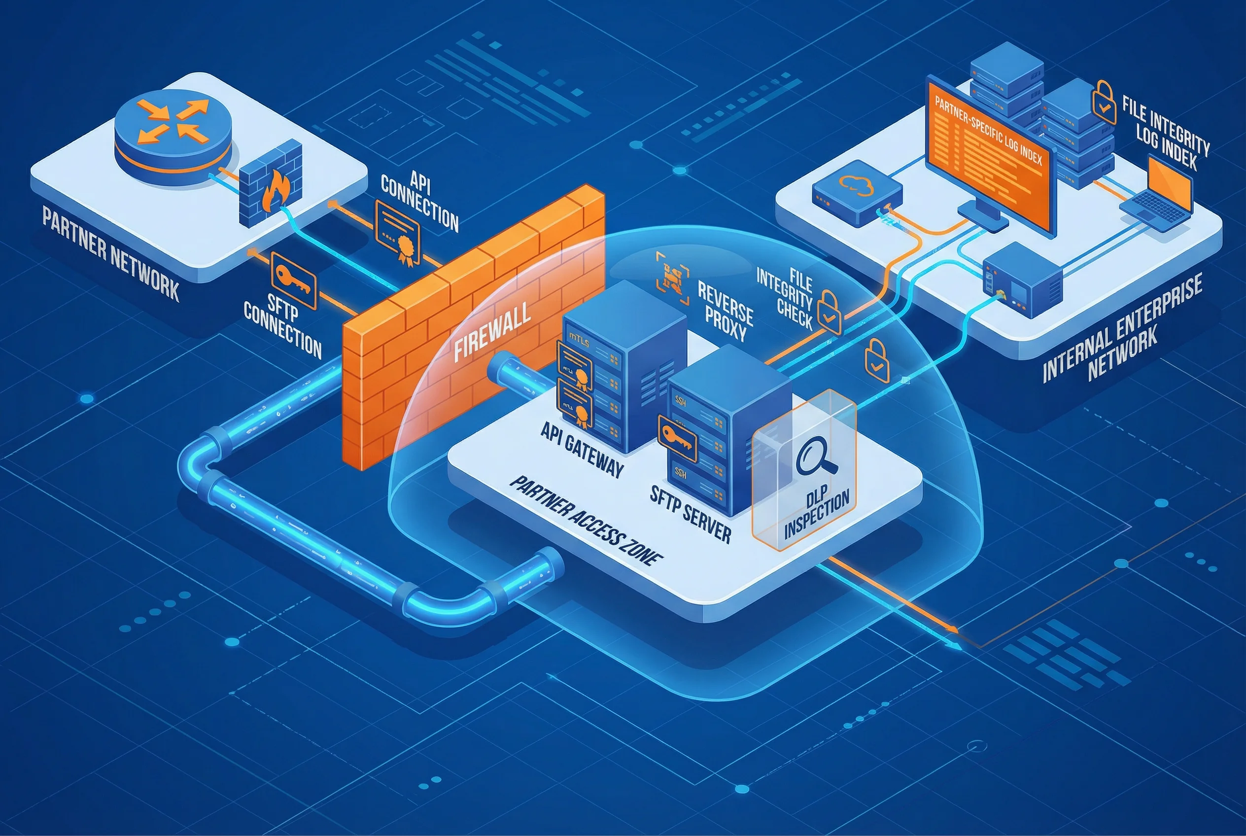
Partner integrations introduce external identities and networks that must be strictly isolated from internal zones. This scenario creates a dedicated Partner Access Zone containing an API gateway for structured data exchange and an SFTP server for file transfers, both accessible only through a reverse proxy. A firewall enforces strict separation between the partner zone and internal networks. mTLS certificates are issued per-partner for API connections, while SSH key pairs are used for SFTP. An optional DLP inspection module can be inserted for regulated data flows. Partner-specific log indexes in the SIEM enable targeted investigation without exposing internal telemetry.
Scenario E — Cloud-to-On-Premises Hybrid Connectivity
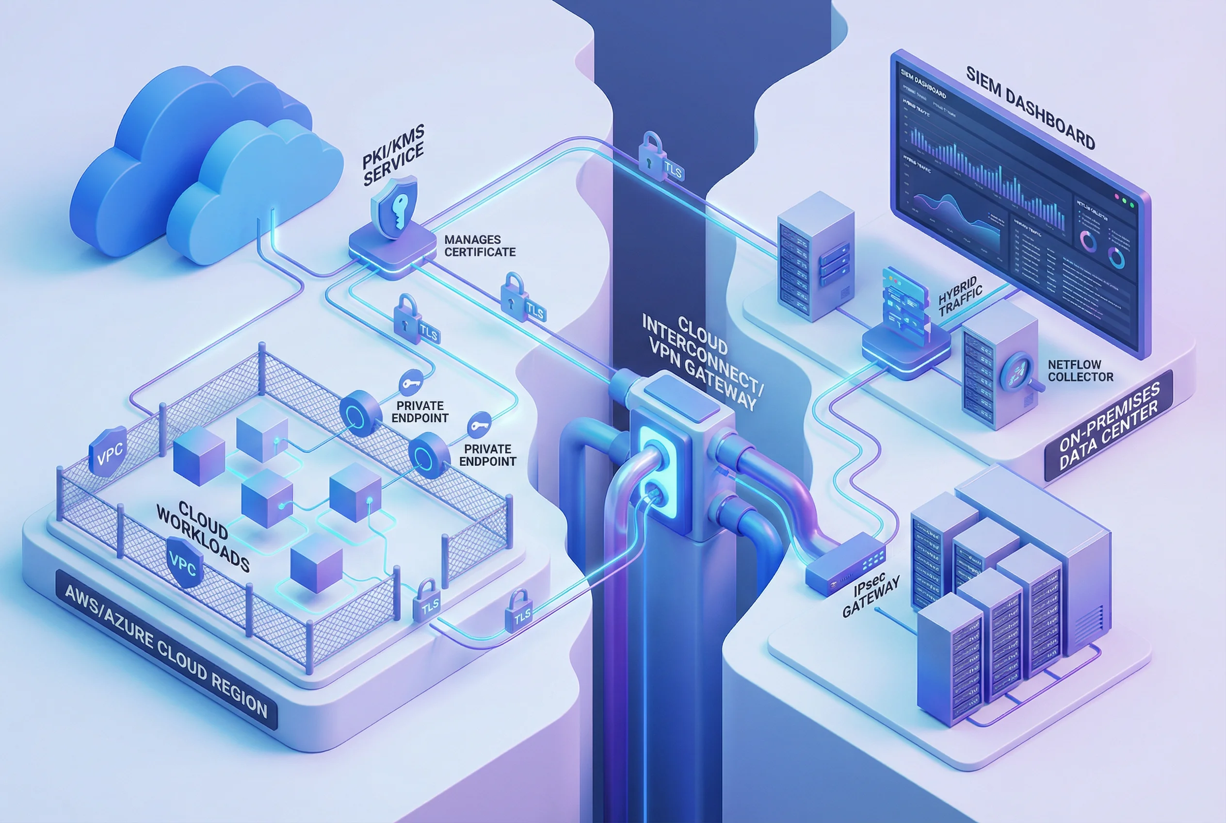
Hybrid cloud deployments require consistent security controls across both cloud and on-premises environments, with a unified PKI/KMS managing certificates for workloads on both sides. This scenario uses cloud-native private endpoints to eliminate public internet exposure for cloud-to-on-premises API calls, combined with an IPsec/VPN gateway for bulk data flows. The on-premises PKI issues certificates that are trusted by cloud workloads, ensuring mTLS is maintained end-to-end. NetFlow from the on-premises edge and cloud VPC flow logs are both ingested by the SIEM for a unified view of hybrid traffic.
Scenario F — Privileged Admin Access via SSH Bastion
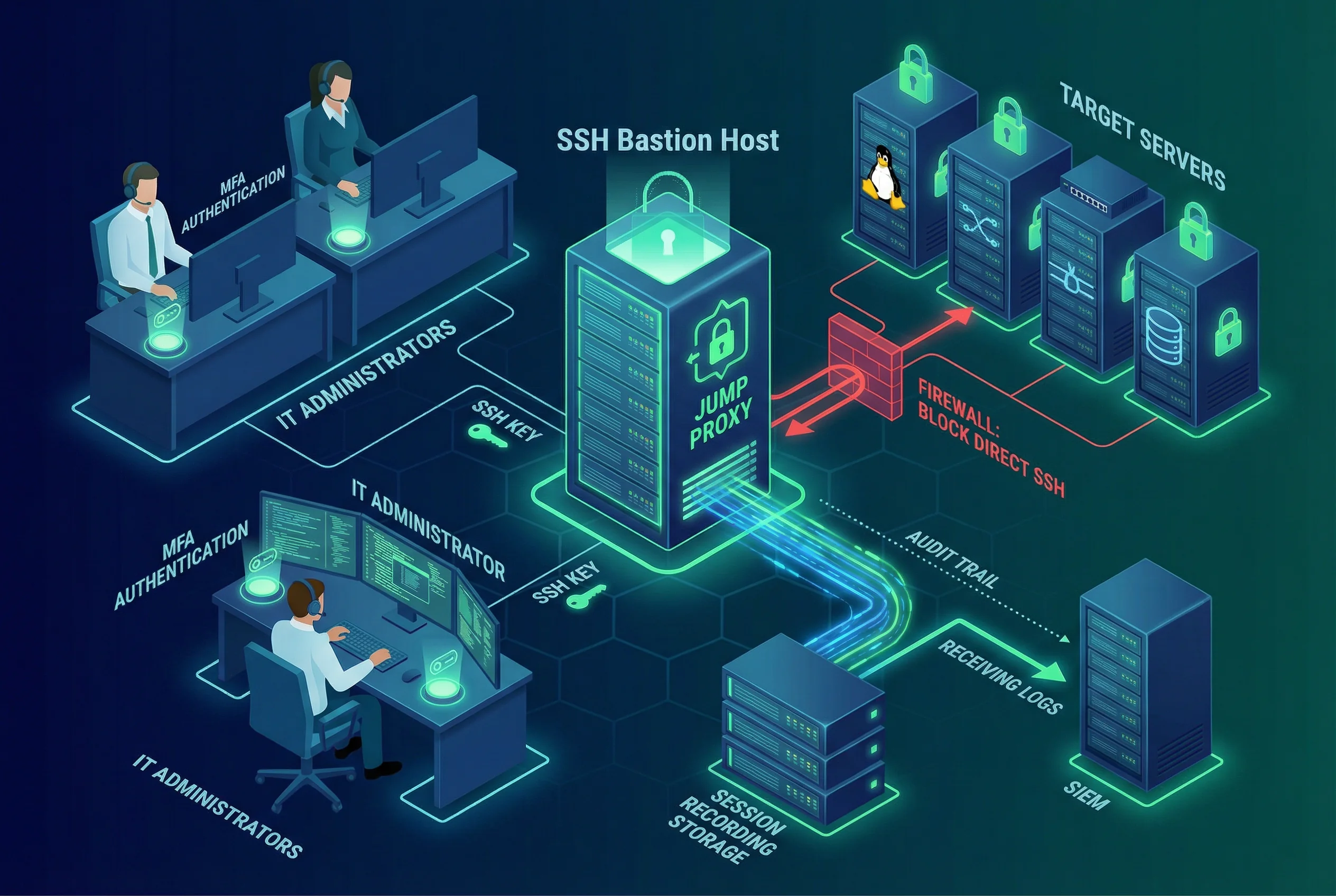
Direct SSH access to production servers is one of the most common sources of credential theft and lateral movement. This scenario eliminates direct admin access by routing all privileged sessions through a hardened SSH bastion host with MFA enforcement. The bastion records all session activity to a tamper-evident storage system and exports session metadata to the SIEM. Firewall rules block all direct SSH connections to target servers, ensuring the bastion is the sole ingress path. SSH key pairs are rotated regularly, and access rights are reviewed quarterly to remove stale accounts.
Scenario G — OT/IoT Secure Data Collection
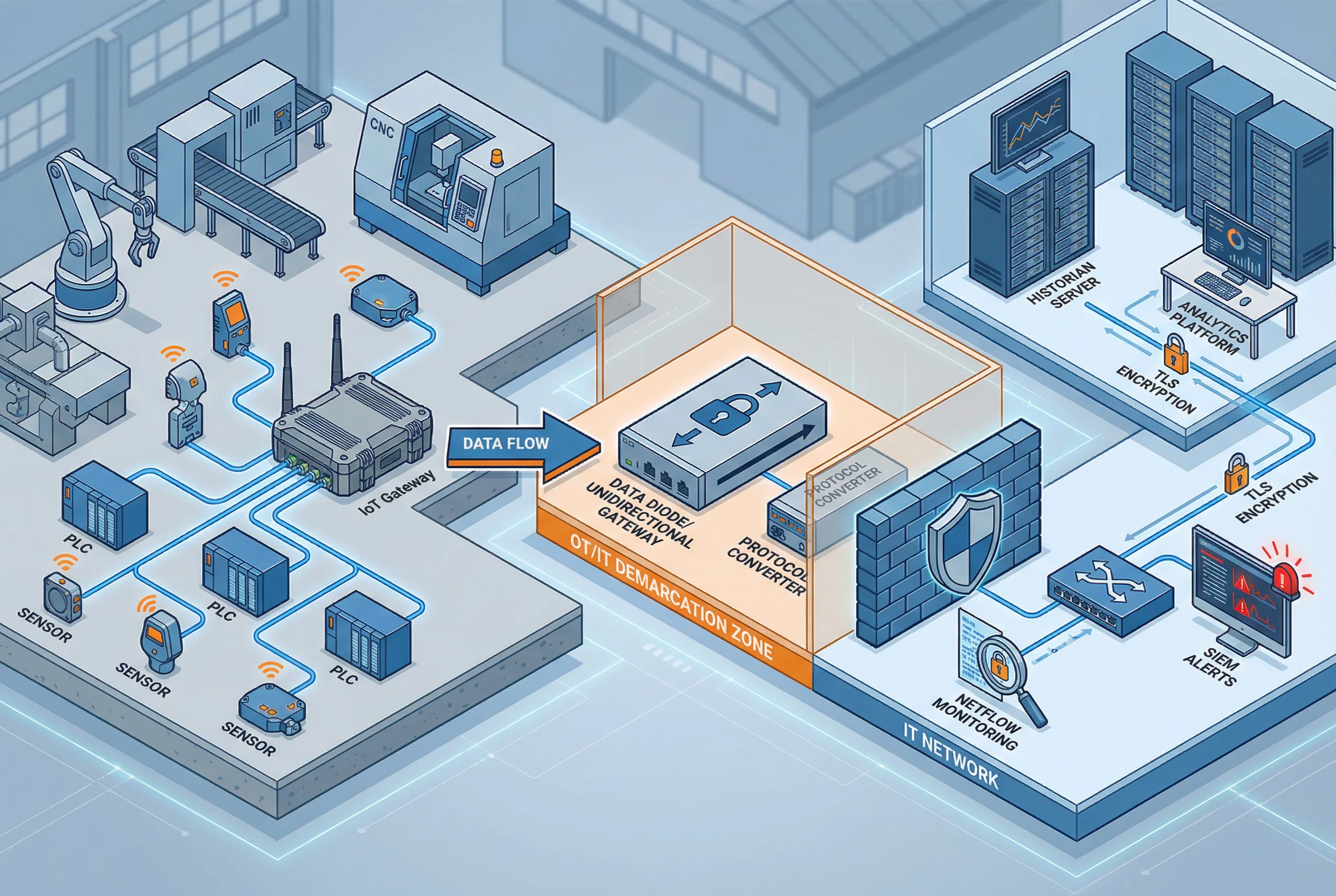
Operational technology (OT) and industrial IoT environments present unique challenges: legacy protocols, air-gap requirements, and the need to collect telemetry data without exposing control systems to IT networks. This scenario uses a data diode or unidirectional security gateway at the OT/IT demarcation zone to enforce one-way data flow from the factory floor to IT analytics systems. A protocol converter bridges industrial protocols (Modbus, OPC-UA) to standard IT formats. TLS encryption is applied on the IT side for historian and analytics connections, while the OT side remains isolated. NetFlow monitoring and SIEM alerts cover the IT segment.
Scenario H — Zero Trust Network Access (ZTNA) for Remote Workers
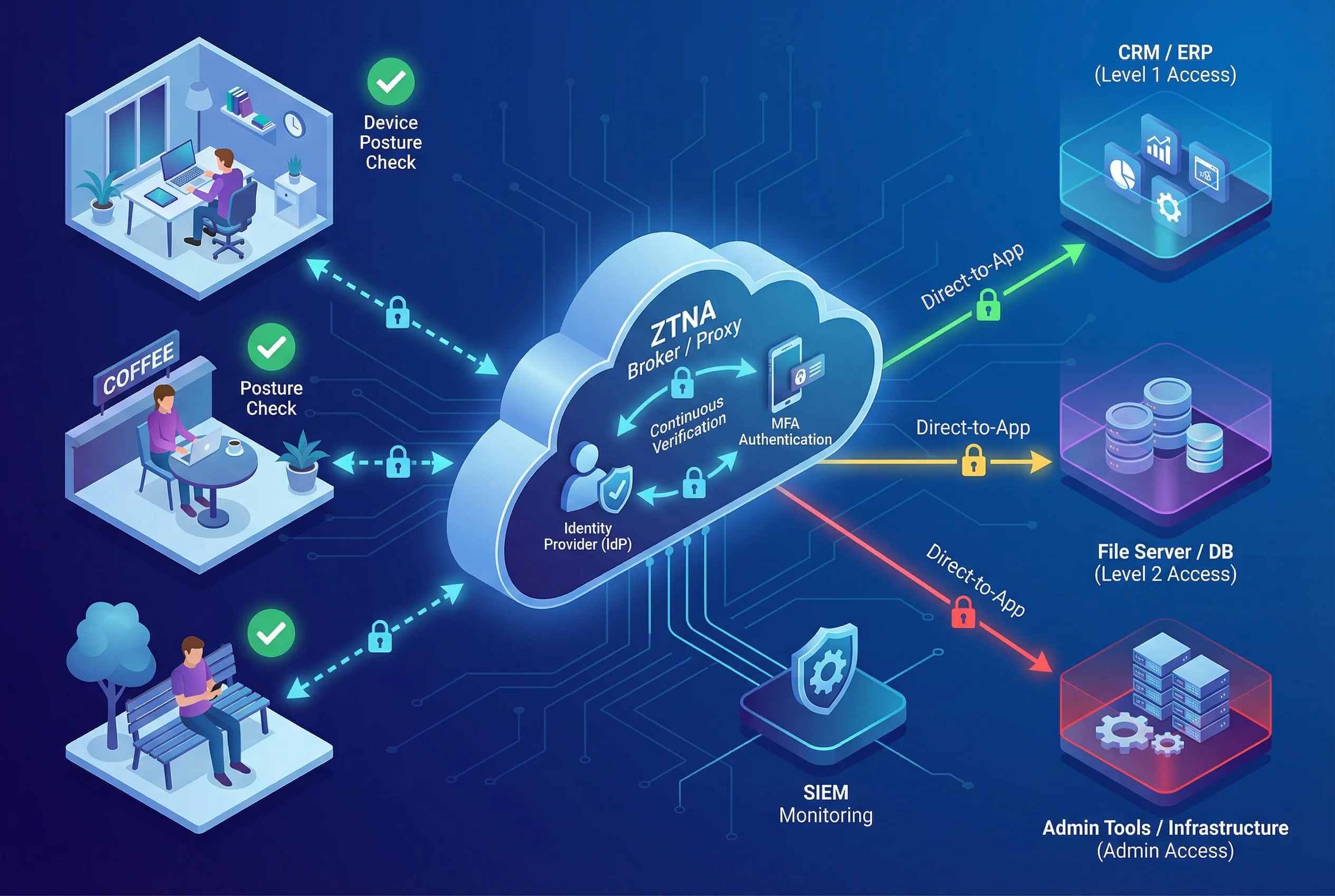
Traditional VPN-based remote access grants broad network access after a single authentication event, creating significant lateral movement risk. ZTNA replaces this with a continuous verification model where every access request is evaluated against identity, device posture, and context. This scenario deploys a cloud-hosted ZTNA broker that integrates with the enterprise identity provider (IdP) for MFA-backed authentication. Each application is individually protected, and access is granted per-session based on real-time posture signals. SIEM monitoring covers all access decisions, and micro-segmentation prevents lateral movement even if a session is compromised.
Scenario Comparison Summary
The table below provides a consolidated comparison of all eight scenarios across the key selection dimensions, enabling engineers to quickly identify the most relevant reference blueprint for their use case.
| Scenario | Traffic Type | Primary Protocol | Identity Binding | Key Control | Observability | Compliance Fit |
|---|---|---|---|---|---|---|
| A — Internet API | North-South | TLS 1.3 + WAF | OAuth 2.0 / JWT | Gateway-terminated | SIEM + NetFlow | PCI DSS, SOC 2 |
| B — Microservices mTLS | East-West | mTLS (mesh) | SPIFFE/SVID | Automated (mesh CA) | SIEM + Tracing | SOC 2, ISO 27001 |
| C — IPsec Replication | Site-to-Site | IPsec IKEv2 | IKE PSK / Cert | Periodic rekey | NetFlow + SIEM | ISO 27001, NIST |
| D — Partner B2B | North-South | HTTPS mTLS + SFTP | Per-partner cert | Per-partner PKI | Partner log index | ISO 27001, GDPR |
| E — Hybrid Cloud | North-South + S2S | TLS + IPsec | Unified PKI | Cloud + on-prem KMS | VPC Flow + NetFlow | ISO 27001, CSA CCM |
| F — SSH Bastion | Admin/Privileged | SSH-2 | SSH key + MFA | Key rotation (90d) | Session recording | PCI DSS, SOC 2 |
| G — OT/IoT | OT→IT (one-way) | Data Diode + TLS | IoT Gateway cert | IT-side PKI | IT NetFlow + SIEM | IEC 62443, NIST |
| H — ZTNA Remote | User-to-App | ZTNA + TLS | IdP + MFA + Posture | Session-scoped | SIEM (all decisions) | NIST ZTA, ISO 27001 |