Installation & Debugging
11.1 Installation Requirements
A successful installation of the critical data transmission security system requires careful preparation of the physical environment before any equipment is delivered to site. The installation requirements cover five domains: physical space and rack infrastructure, power and grounding, environmental controls, network pre-provisioning, and personnel qualifications. Failure to meet any of these requirements before installation begins is the leading cause of installation delays and post-installation reliability issues.
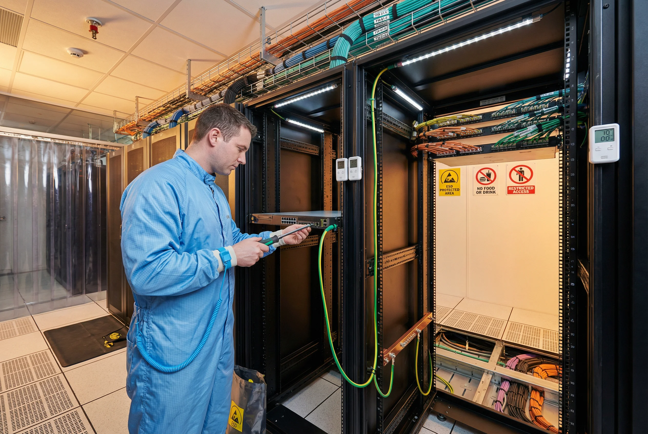
The photograph below illustrates a compliant installation environment, showing the key elements that must be in place before equipment installation begins: proper ESD protection, organized cable trays, grounded racks, environmental monitoring, safety signage, and qualified personnel with appropriate tools and PPE.
11.2 Pre-Installation Site Requirements
All site requirements must be verified and documented before equipment is delivered. The site survey checklist below must be completed and signed off by the facilities manager and the installation engineer at least five business days before the scheduled installation date.
| Domain | Requirement | Specification | Verification Method | Responsible Party |
|---|---|---|---|---|
| Physical Space | Rack Space | Minimum 2U free per appliance; 42U rack recommended; 1000mm depth | Physical measurement; rack diagram | Facilities |
| Floor Loading | Minimum 500 kg/m² (raised floor); 1000 kg/m² (concrete) | Structural engineer certificate | Facilities | |
| Aisle Width | Minimum 1200mm front aisle; 800mm rear aisle | Physical measurement | Facilities | |
| Power | Circuit Capacity | Dedicated 20A circuit per rack; dual-feed from separate distribution boards | Electrician sign-off; circuit breaker labeling | Facilities / Electrician |
| UPS Coverage | UPS on each power feed; minimum 10-min runtime at full load | UPS load test; runtime calculation | Facilities | |
| Grounding | Ground resistance < 1 Ohm at each rack; bonded to facility ground bus | Ground resistance measurement; certificate | Electrician | |
| Environment | Temperature | 18–27°C operating range; monitored and alarmed | Temperature sensor reading; alarm test | Facilities |
| Humidity | 40–60% RH; monitored and alarmed | Humidity sensor reading; alarm test | Facilities | |
| Fire Suppression | Clean agent (FM-200 or Novec 1230) or pre-action sprinkler; no wet pipe in server room | Facilities inspection; fire safety certificate | Facilities / Fire Safety | |
| Network | VLAN Pre-provisioning | Management, production, and quarantine VLANs created on upstream switch before installation | Switch configuration review | Network Team |
| IP Address Allocation | Management IPs, gateway IPs, and DNS servers allocated and documented before installation | IP address management (IPAM) review | Network Team | |
| Personnel | Engineer Qualification | Lead engineer: vendor-certified or equivalent; minimum 2 years data center installation experience | CV review; certification verification | Project Manager |
| ESD Training | All personnel handling equipment must have completed ESD awareness training within 12 months | Training record review | Project Manager |
11.3 Step-by-Step Installation Procedure
The installation procedure must be followed in the sequence below. Each step must be completed and verified before proceeding to the next. Any deviation from this sequence requires written approval from the project manager and must be documented in the installation log.
- Site Verification (Day -1): Complete site survey checklist; confirm all pre-installation requirements met; photograph site before equipment delivery.
- Equipment Delivery and Inspection: Inspect all packages for shipping damage; verify serial numbers against purchase order; check firmware hash on USB drives; do not power on equipment yet.
- ESD Preparation: Deploy anti-static mat; connect ESD wrist straps; verify ground connection of mat and straps before handling any equipment.
- Rack Rail Installation: Install rack rails per vendor instructions; verify rail depth adjustment matches appliance depth; torque rail screws to specification.
- Appliance Mounting: Mount appliances in planned rack positions (heaviest at bottom); do not over-tighten rack screws; verify appliance is level and fully seated on rails.
- Power Cabling: Connect power cables to PDUs; verify dual-feed connection for redundant PSUs; do not power on yet; label all power cables.
- Network Cabling: Connect management cables first; then production interfaces; then out-of-band interfaces; label both ends of every cable immediately after connection.
- Console Access Setup: Connect console cables; verify console access to each appliance before powering on; prepare terminal emulator with correct baud rate (typically 9600 or 115200).
- Initial Power-On: Power on appliances one at a time; verify POST completes without errors; check all indicator LEDs; do not proceed if any critical errors are displayed.
- Firmware Verification and Update: Verify installed firmware version; compare to approved version on USB drive; update if required; verify hash after update.
- Initial Configuration: Apply baseline configuration from approved template; set management IP, hostname, NTP, and SNMP; change all default passwords immediately.
- Security Hardening: Apply security hardening checklist; disable unused services and ports; enable logging; configure SNMP v3 only; apply ACLs to management interfaces.
- Functional Verification: Execute FAT test cases from Chapter 10; document results; remediate any failures before proceeding.
- Asset Tagging and Sealing: Apply asset tags; record in CMDB; apply tamper-evident seals to chassis screws; photograph seals; record seal numbers in installation log.
- Documentation Handover: Complete as-built documentation; hand over to customer; obtain acceptance sign-off.
11.4 Common Issues and Troubleshooting
The troubleshooting guide below covers the most frequently encountered issues during installation and initial configuration, with diagnostic steps and resolution procedures for each.
| Issue | Symptoms | Likely Cause | Diagnostic Steps | Resolution |
|---|---|---|---|---|
| TLS Handshake Failure | Connection refused; SSL error in client logs | Certificate mismatch; cipher mismatch; clock skew | Check cert CN/SAN; verify cipher suite overlap; check NTP sync | Re-issue cert with correct SAN; align cipher suites; sync NTP |
| IPsec Tunnel Down | No traffic through tunnel; IKE SA not established | PSK mismatch; IKE version mismatch; NAT-T issue | Check IKE logs; verify PSK; check IKE version config on both ends | Correct PSK; align IKE version; enable NAT-T if behind NAT |
| Certificate Revocation Check Failure | Valid cert rejected; OCSP timeout in logs | OCSP responder unreachable; firewall blocking port 80 | Test OCSP URL from appliance; check firewall rules | Open firewall for OCSP responder; or configure OCSP stapling |
| SIEM Log Gap | Events missing in SIEM; gap in timeline | Syslog UDP packet loss; TLS syslog cert expired; disk full | Check syslog queue; verify TLS cert; check SIEM disk space | Switch to TCP syslog; renew cert; expand SIEM storage |
| NAC Authentication Failure | Device placed in quarantine VLAN unexpectedly | RADIUS server unreachable; EAP-TLS cert expired; posture check failure | Test RADIUS connectivity; check device cert; review posture policy | Fix RADIUS connectivity; renew device cert; update posture policy |
| High CPU on Security Appliance | Throughput degraded; latency increased | Crypto offload not enabled; excessive logging; DDoS | Check CPU utilization by process; verify hardware crypto offload; check traffic rate | Enable hardware crypto offload; tune log verbosity; implement rate limiting |